
Stephan Eder, Director, Business Unit Climate Technology, Hoval, elaborates on the differential pressure at the plate heat exchanger and the importance of paying attention to the arrangement of the fans.
There are different pressures on the supply and extract side of a ventilation system – depending on the installed components and the arrangement of the fans. This becomes particularly clear in the plate heat exchanger, which is acted upon by both air streams and where two different pressures prevail at one location, separated only by a thin plate. The difference between these two pressures is called the differential pressure; it influences a possible leakage and may deform the plate due to the resulting surface force. This results in a change of the plate spacing and thus the pressure loss. The differential pressure for the respective plate heat exchanger must therefore be limited for the planning of the ventilation system and its trouble-free operation.
The differential pressure in detail
The differential pressure in a plate heat exchanger depends significantly on the fan arrangement and the installed components. This can best be explained by the possible variants of a typical ventilation system (Fig. 1). A cross-flow heat exchanger (pressure drop 140 Pa) is chosen as the heat exchanger, as this is the most complex in terms of differential pressure. The further installed components and their pressure losses are ""normal"" for 2018. For the fresh air fan, the positions A and B are possible, for the extract air fan C and D are possible (1 = extract air EXT; 2 = supply air SUP)."
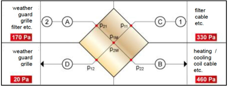
Fig. 1: Variants of a ventilation system
The pressures for the four possible variants are summarised in Table 1.
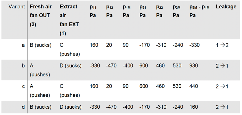
Table 1: Cross-flow plate heat exchanger pressures
Before discussing the results, it is important to realise that the differential pressure in the cross-flow manifold is not constant; it changes with the flow due to its own pressure loss. Figure 2 shows this as an example of variant a, which is widely used in Germany in particular:
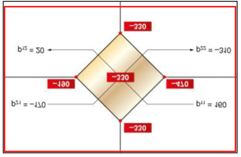
Fig. 2: The local differential pressure
The following points are important:
- The differential pressure is obtained by subtracting the pressure on the extract air p1 from the pressure on the supply air p2. This also defines the pressure gradient that is important for any leakage:
- Negative differential pressure → Leakage to SUP → undesirable
- Positive differential pressure → Leakage to EXT → acceptable
Attention: Overpressure and underpressure add up.
- The indicated pressure differences at the corner points show how clearly the values - depending on the position - differ. The question now is which value is used for the definition. The sensible (and usual) one is the mean value that is set in the centre of the exchange.
- For extreme values, check which differential pressures occur when a fan is switched off (e.g. in start-up mode).
- These statements for the cross-flow heat exchanger are also valid for the counter-flow exchanger.
The following should be noted with regard to the various fan arrangements in Table 1:
- This arrangement is used in most cases. It saves space and allows mixed air operation. And the nominal air flow rates correspond to the fan outputs. The disadvantage is the pressure drop towards the supply air; in case of leaks, extract air is transferred to the supply air. A "tight" plate heat exchanger is therefore a prerequisite for keeping any leakage at a low level. The differential pressure (p2M - p1M) is moderate at -330 Pa.
- In this variant, the differential pressure is highest at 930 Pa, but the pressure drop is towards the extract air. The arrangement of the fans one above the other - as in a) - saves space.
- This case is rather unusual. Since both fans push with respect to the heat exchanger, the pressure drop is not clearly defined; it depends on the pressure losses of the installed components.
- This arrangement is the best solution in terms of differential pressure, which is only 160 Pa. The pressure drop is also advantageous towards the extract air. The disadvantage is the large space requirement due to the arrangement of the fans upstream and downstream of the heat exchanger.
As already mentioned several times, the differential pressure has a decisive influence on the quantity and direction of leakage in the event of leaks. It also influences the plate profiling, in other words the plate spacing, and thus the pressure loss.
Deformation of the plates due to differential pressure
Plate heat exchangers in ventilation technology are usually made of thin aluminium plates with a thickness of only 0.05-0.15 mm. A special, manufacturer-specific profiling ensures a certain stability, but this cannot prevent the plates from deforming at higher differential pressures (Fig. 3).
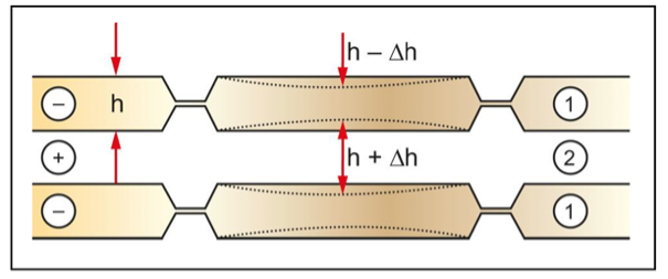
Fig. 3: Schematic representation of the plate deformation
Fig. 3 shows the flow of extract air 1 and fresh air 2 through the plate heat exchanger. There is a differential pressure from the fresh air to the extract air, which compresses the plates between the spacers (e.g. knobs, spacer bars) by Δ h. This reduces the cross-section of the extract air and increases the pressure loss. At the same time, the cross-section on the fresh air is increased; the pressure loss decreases. In highly simplified terms, the effect of the deformation Δ h on the pressure loss under otherwise constant conditions (volume flow, temperature, etc.) can be represented as follows:
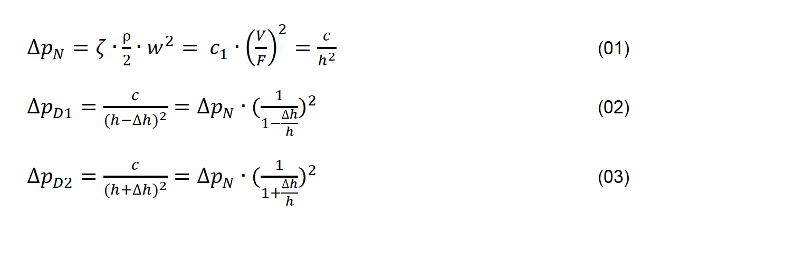
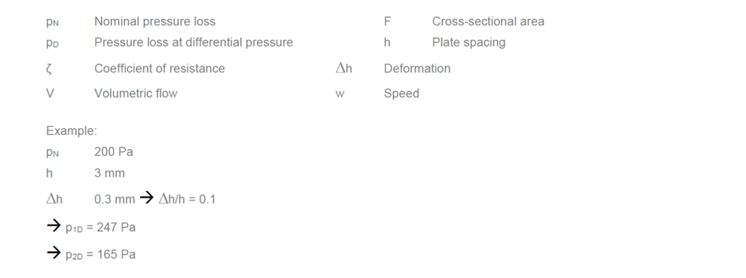
The example shows that the total pressure loss of both air streams increases slightly when the plates are deformed. With regard to EU 1253-2014, the SFP value should therefore be checked.
Fig. 3 and the formulas show that the change in pressure loss at a given differential pressure depends on the relative deformation Δ h/h, i.e. ultimately on the plate spacing. The smaller the plate spacing, the more a deformation affects the pressure loss and vice versa. This insight is important for high-performance applications where small plate spacings are necessary. Especially counter-flow heat exchangers should use stable plates.
The previous considerations assume that the plates deform elastically, i.e. the change in the plate spacing increases and decreases with the differential pressure. This is comparable to a spring. It is different when the deformation becomes too large at high differential pressure and plastic changes occur. If the differential pressure now decreases (or the fans are switched off), the deformation still remains: the heat exchanger is defective; leaks and unpredictable technical values are to be expected.
In order to specify the permissible differential pressure for a certain heat exchanger, the manufacturer must therefore observe two criteria:
- Within the permissible limit value, no plastic deformations are allowed to occur; a safety margin is necessary. The reference value for this criterion is the maximum differential pressure and not (as usual) the mean value! (see Fig. 2)
- For elastic deformation, it is necessary to estimate or measure the increase in pressure loss resulting from the differential pressure. The user can then decide on the application himself with the corresponding documentation (diagram 1). A pressure drop increase of more than 40% as a result of the differential pressure should, however, be avoided.
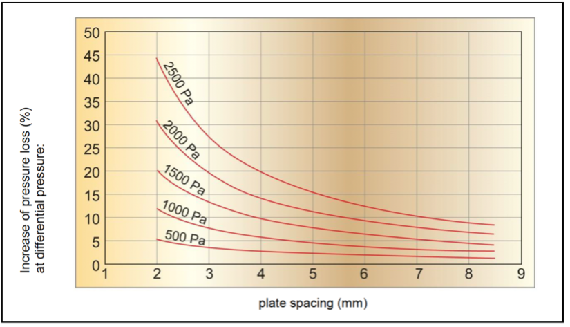
Diagram 1: Dependency between pressure loss and plate spacing
Summary
Differential pressures in a plate heat recovery unit of a ventilation system are unavoidable between the two air flows. However, by paying attention to the arrangement of the fans, they can be kept within reasonable limits. Planning and execution of heat recovery requires documents dealing with the effects of differential pressure. If one considers that the values in Table 1 are relatively "high quality" and can, therefore also be significantly higher in some systems, the permissible differential pressures should be at least 1500 Pa, or better still 2000 Pa. This should provide the desired reserve for planning and implementation changes.